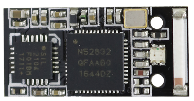
Board
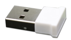
A usb dongle from the market that includes a 2104 serial to usb converter. Keyword search on shopping websites : nRF52832 USB dongle. Aka "nRF52832-YJ-17017-USB-UART"
Software
RF to Serial Gateway
The node connected through serial port will report messages in text format
- Local Events
Upon startup such message is sent
nodeid:75;channel:10;reset:12. Listening
Upon activation of the uicr config
is_listening the node starts acting as a gatewy that will report messages through serial in text moderssi:-50;id:73;ctrl:0x81;src:73;alive:68;tx_power:03. commands requests and responses
It is possible to reconfigure the Node on runtime and manage manage a mesh network by sending messages
cmd:0x0102
cmd:0x<command id><arguments>| Command id | Function | Parameters |
|---|
Command examples
Set channel 10/0x0A
cmd:0x030Aget channel
cmd:0x04Set Tx Power to -4dBm/0xFC
cmd:0x05FCSet UICR e.g. RF Channel @ CUSTOMER[1] to channel 10
cmd:0x0B010ASend message, directed (not broadcast) with ttl = 2, ping(75/0x4B) from 73/0x49
msg:0x7201494BSend message to execute on the RF target node 75/0x4B the command Set Tx Power to -4 dBm
msg:0x72EC494B05FCSend message to execute on the RF target node 75/0x4B the command Set channel to 0x0A
msg:0x72EC494B030ASend request to execute on the RF target node 75/0x4B the command Set channel to 0x0A
The only difference to the previous example is that an intermediate ack for the request is not required before getting the response
msg:0x22EC494B030A Switch between serial SERIAL and LOG over UART
run
make confthen switch both flags :
- nRF_Log/NRF_LOG_BACKEND_UART_ENABLED
- Application/APP_SERIAL_ENABLED don't forget to save
Serial mode
- NRF_SERIAL_MODE_IRQ flag is not used by the driver and has equivalent function as NRF_SERIAL_MODE_DMA
- ser_send() must be used with a variable in memory as DMA cannot read from Code in Flash
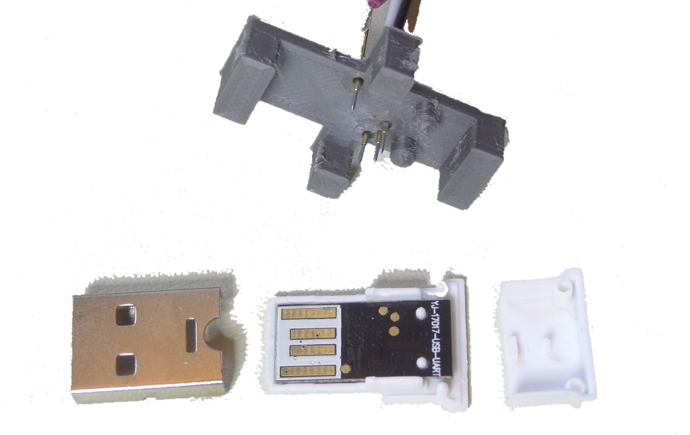
Flashing
outside
inside
Components side
SWDIO pins side

pinout
| nRF52 | pin |
|---|
Needle adapter
Making a needle adapter is made easier with 3d printing. The used pogo pin is seen below

The adapter model still in preparation can be found here. It should look something like this:
Adapter model
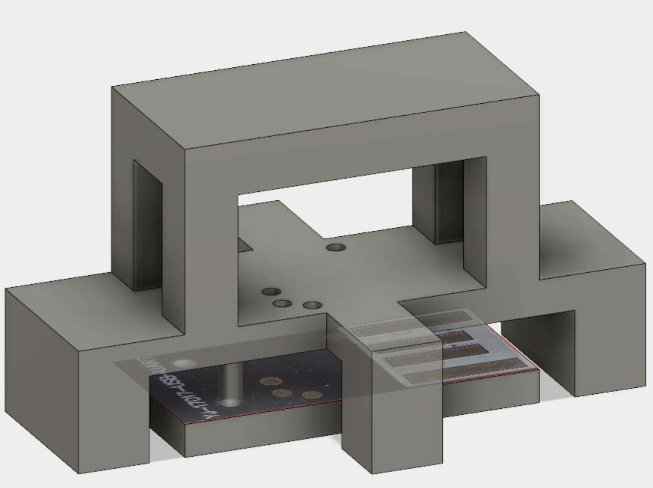
Adapter